The drawing your builder works from, off the same model as the picture.
A floor plan with every unit dimensioned and coded, an elevation of each wall viewed from inside the room, and the Setout Sheet with every service point at its height. They come off the same model as the 3D view and the realistic image, so the plan and the picture cannot disagree.
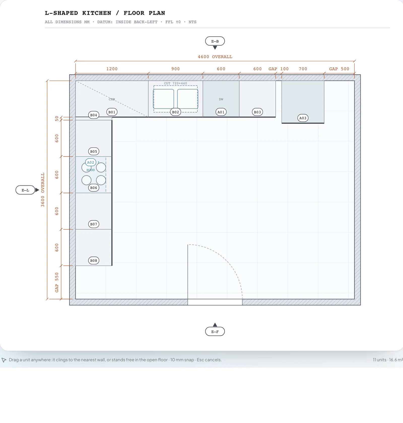
What is on the plan
- Dimension chains
- The overall room and every unit along each wall, with the gaps between them, in the unit system you choose.
- Unit codes
- B01, A02, and so on: a permanent code per unit that matches the schedule and the elevations, so a conversation on site can point at one thing.
- Cut-outs and symbols
- Sink and hob cut-outs at their size, appliance abbreviations, the hood as an overhead dashed outline, door swings and window openings.
- Elevation markers
- E–B, E–L, E–F: which sheet shows each wall, drawn on the plan where an architect would put them.
- Sheet furniture
- A title and convention note, a graphic scale bar, and a title block with sheet, content, units, client, revision and status.
One sheet per wall, viewed from inside the room.
Worktop and tile heights, the wall cabinets and the hood, the ceiling, every unit's width and code, and each service point with its height above the finished floor. Units on the neighbouring wall that meet this one are hatched, so a return is never mistaken for a gap.
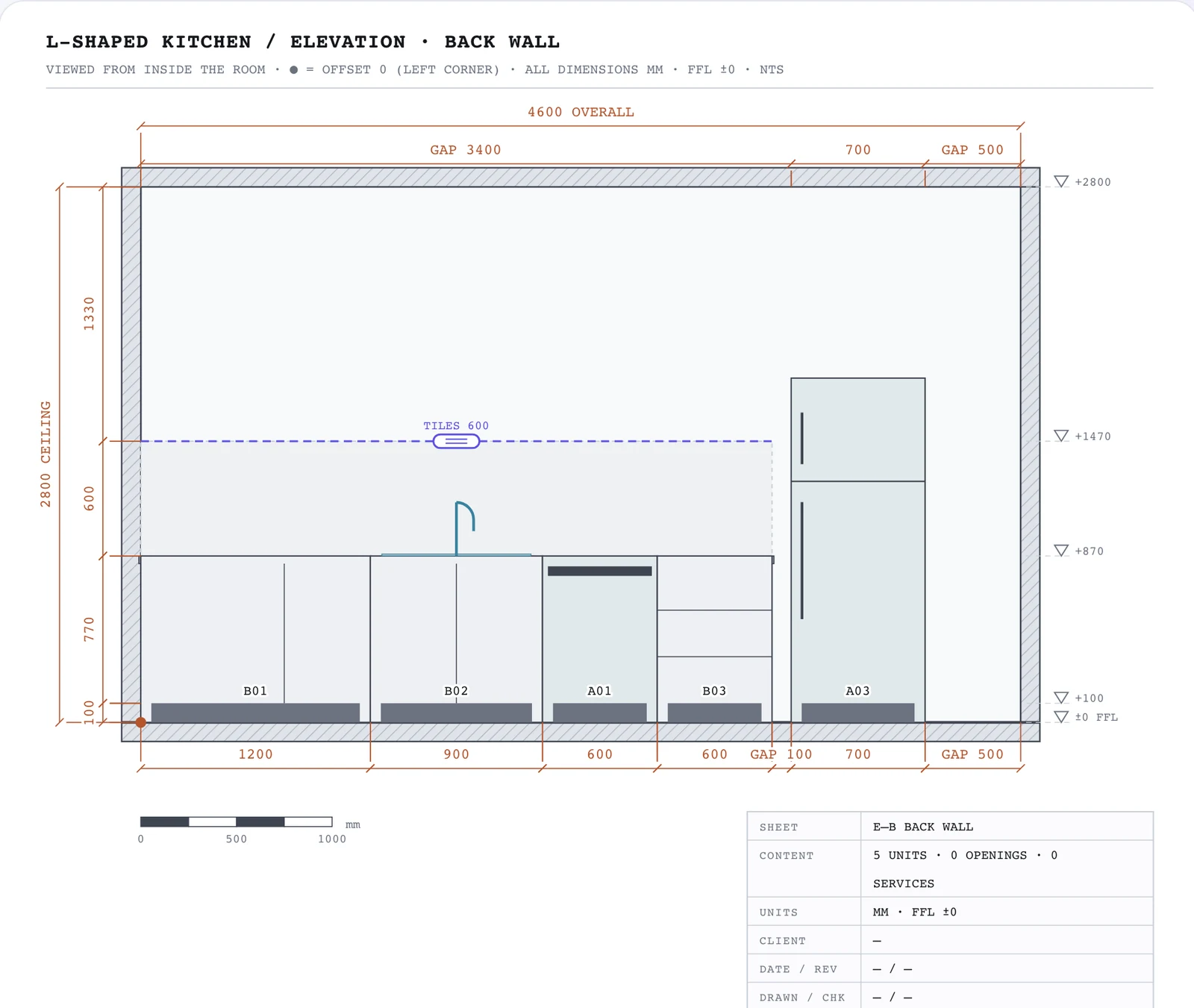
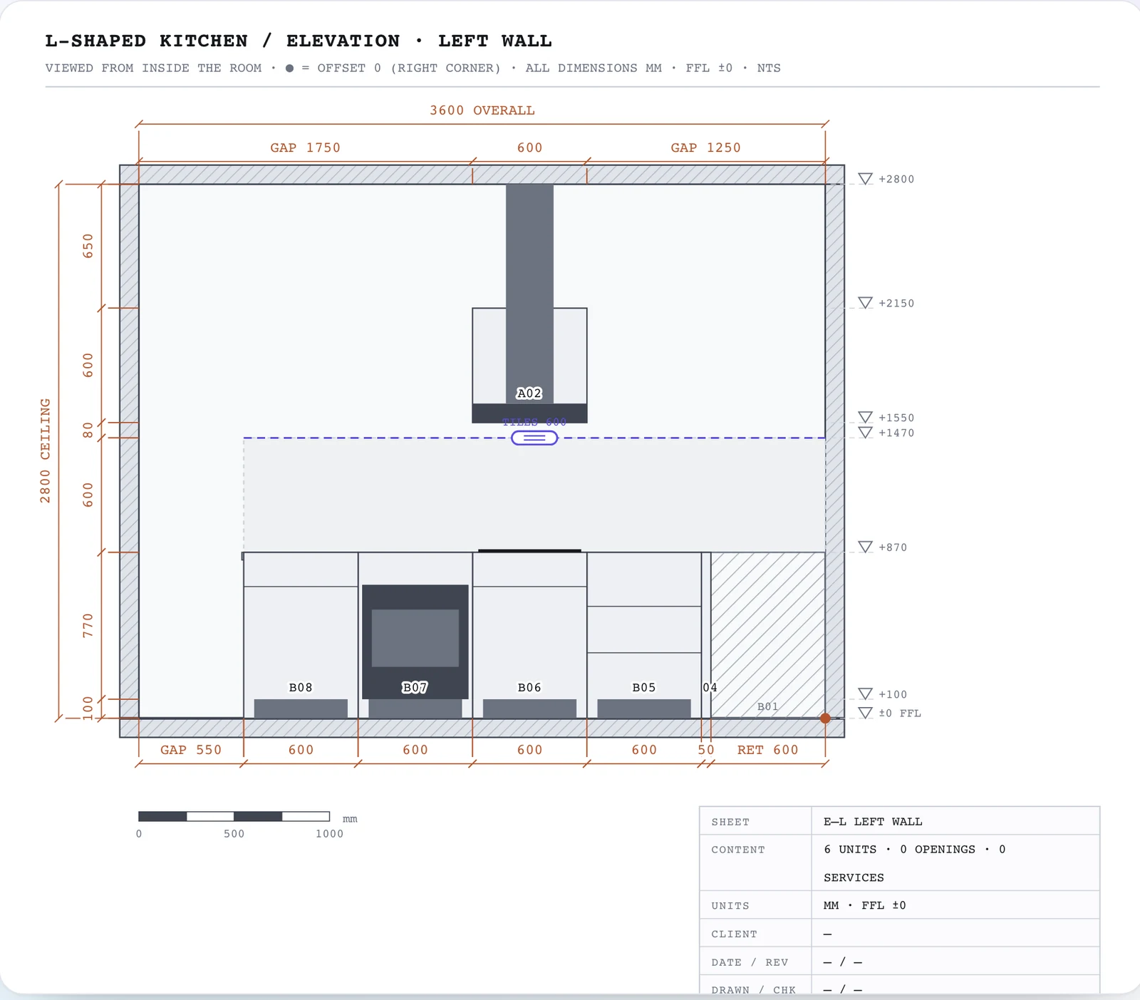
Read more about what an elevation is for on the elevations page.
A pretty render never stopped a socket being left out.
The floor plan below reads the same geometry as the 3D kitchen: the L-shaped worktop, sink opening, hob, refrigerator and service locations. Dimensions come from the model, so the drawing and the kitchen stay in agreement.
Read the setout from the inside back-left corner. The schedule gives each electrical point’s wall offset and height above finished floor level. This is the demo model reference; confirm site measurements, appliance clearances and manufacturer cutout templates before issuing a fabrication drawing.
- 1Small appliances1150 mm
- Two outlets, not one. The kettle and the mixer grinder both end up living on the counter.
- 2Range hood / chimney2050 mm
- Behind the hood so the plug is hidden. Confirm hood height before anything is chased.
- 3Water purifier1250 mm
- Plus a drain point within 600 mm, or the waste line runs across a finished backsplash.
- 4Refrigerator1900 mm
- Dedicated circuit, never shared with the small-appliance run, and above the fridge so the plug stays reachable without pulling the unit out.
- 5Microwave1400 mm
- Sits above the microwave's own height so the flex drops to it, clear of the backsplash band.
- 6Built-in oven1200 mm
- A 20 A double-pole isolator above the worktop, beside the bay. The oven's own outlet goes in the neighbouring cabinet, never behind the appliance.
- 7Cooktop ignition1100 mm
- Offset 300 mm behind the rear burner, so the cable never runs over a flame and the plate stays clear of the window.
K–01 · Floor plan, dimensions & service setout
Top-down plan from the 3D model · dimensions in millimetres · use written dimensions, not screen scale. Enlarge to inspect dimension chains. Plumbing, wall thickness and structural openings require site confirmation.
PDF for the builder, SVG for anyone who wants to mark it up.
Export PDF prints the whole pack, plan, elevations and schedule, from the browser. Each drawing can also be downloaded on its own as SVG, which opens in any vector editor and scales without going soft.
The drawings carry standing notes about what they are and are not: unit sizes are from the schedule, walls are drawn 100 mm thick and indicative, and site, services and appliance specifications are to be confirmed before ordering. You can rewrite or add notes per project.
Questions
The wall is still bare. That is the good news.
Build it here first — the room, every appliance, the finishes you are weighing up — and walk into the conversation with your builder holding a photograph and a plan instead of a description. Start with your room and make it your own.
Your kitchen starts here
Sign in with Google to open your studio and start a kitchen project.
Start designing free